
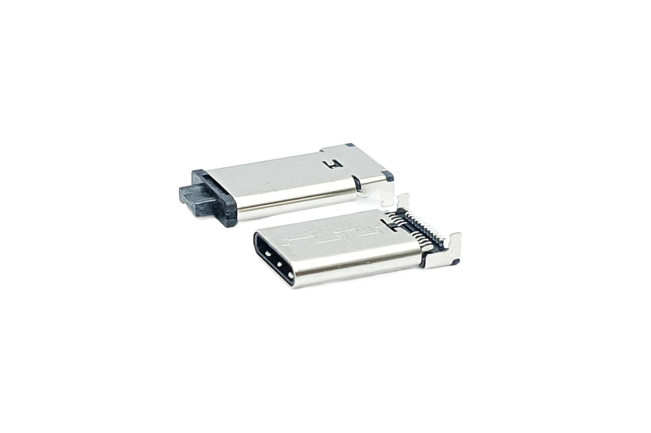
USB Type-C connectors use a 24-contact, oval-shaped, reversible design and can support high-speed data transmission and higher-power delivery depending on the system configuration. USB Type-A connectors, meanwhile, offer mature and extensive peripheral compatibility.
When designing a new product, should the USB interface be Type-C or Type-A? Although the two look very different, what are the functional differences? Many engineering teams only discover at the prototyping stage that the contact structure, data and power specifications, and application and compatibility requirements are not aligned. Understanding these three points before selection helps reduce last-minute redesigns and delays before mass production.
Contact Structure and Reversible Design: How Do Type-C and Type-A Differ?
A USB Type-C connector has 24 contacts and a reversible oval-shaped interface measuring approximately 8.4 mm × 2.6 mm, making it much smaller than a traditional USB Type-A Connector. USB Type-A is the familiar rectangular interface. Depending on the USB specification, it commonly has four contacts for USB 2.0 or nine contacts for a SuperSpeed USB Type-A implementation. Its opening measures approximately 12 mm × 4.5 mm, and it can be inserted in only one direction.
Reversible insertion may seem like a small detail, but it directly affects the user experience and mechanical design. Type-C allows users to connect the plug without checking its orientation. Because the structure is more precise, however, tooling, terminal processing, and PCB manufacturing tolerances are generally more demanding than those for Type-A.
Durability also differs. Under USB-IF specifications, USB Type-C connectors are rated for 10,000 mating cycles, while standard USB Type-A connectors are rated for 1,500 cycles. Actual service life also depends on connector construction, materials, plating, manufacturing processes, and the operating environment. Product specifications and test conditions should therefore be reviewed during selection.
| Comparison Item | USB Type-C Connector | USB Type-A Connector |
|---|---|---|
| Interface Size | Approx. 8.4 mm × 2.6 mm, oval-shaped | Approx. 12 mm × 4.5 mm, rectangular |
| Number of Contacts | 24 contacts, symmetrical design | 4 contacts (USB 2.0) or commonly 9 contacts (SuperSpeed) |
| Mating Orientation | Reversible | Single orientation only |
| Mating Durability | 10,000 cycles under USB-IF specifications | 1,500 cycles for standard Type-A under USB-IF specifications |
Data Transfer and Power: How Fast Can Type-C Run, and How Much Power Can It Support?
USB Type-C can support higher maximum data rates. The original USB4 specification supports up to 40 Gbps, while USB4 Version 2.0, released in 2022, increases the maximum to 80 Gbps. USB Type-A may support USB 2.0, USB 3.2 Gen 1 at 5 Gbps, or USB 3.2 Gen 2 at 10 Gbps, depending on the system design. Data speed is determined by the connector, controller, PCB design, and cable together; the same interface shape does not necessarily indicate the same transfer rate.
The difference in power capability can be even more significant. When implemented with USB PD 3.1 and EPR, a fully compatible power source, device, connector, and rated cable can support up to 240 W at 48 V/5 A. USB Type-A is more commonly used with traditional USB power or a specific charging protocol. Not every Type-C port supports USB PD or 240 W. Some Type-C systems may also support DisplayPort Alt Mode, but the host, controller, cable, and display must all support the function.
| Comparison Item | USB Type-C Connector | USB Type-A Connector |
|---|---|---|
| Data Transfer | Depending on the system: USB 2.0, USB 3.2, or USB4; USB4 Version 2.0 up to 80 Gbps | Depending on the system: USB 2.0, USB 3.2 Gen 1 (5 Gbps), or Gen 2 (10 Gbps) |
| Power Delivery | With USB PD 3.1/EPR, a compatible system can support up to 240 W (48 V/5 A) | Typically USB baseline power or a specific charging protocol |
| Video Output | Some systems may support DisplayPort Alt Mode | Does not support USB Type-C alternate-mode video output |
Application and Compatibility: What Should Be Confirmed Before Selection?
The final choice between USB Type-C and USB Type-A should be based on product space, charging requirements, and peripheral compatibility rather than specifications alone. A common mistake is to compare only data rates while overlooking compatibility with existing Type-A peripherals, which may create an additional need for adapters after launch.
The two interfaces currently coexist rather than representing a simple old-versus-new replacement. USB Type-A remains widely used in automotive electronics, industrial equipment, and medical devices because of installed-system compatibility and long-term supply considerations. Confirm the target market and peripheral ecosystem before deciding whether the advantages of Type-C justify a platform change.
| Selection Factor | Consider a USB Type-C Connector When | Consider a USB Type-A Connector When |
|---|---|---|
| Product Space | The device is slim or internal space is limited | The host or peripheral has sufficient enclosure space |
| Charging Requirements | Fast charging or power delivery for high-power devices is required | Power requirements are relatively low |
| Compatibility | The target is a newer consumer-electronics ecosystem or video output is required | Compatibility with existing USB-A peripherals is required |
| Mating Frequency | The portable device is connected and disconnected frequently | The fixed device is connected and disconnected less frequently |
Customization and the Pre-Production Selection Checklist
After the interface type is selected, several PCB and production details still require attention. Both connector types are available with SMT, DIP, or hybrid retention designs. SMT supports low-profile products and automated production, while DIP terminals or shell stakes can provide additional mechanical retention when required. Actual strength depends on the terminals, shell stakes, solder joints, PCB, and complete product structure.
If the product requires a non-standard contact configuration, special shell height, or waterproof design, working with a Custom Connector Manufacturer early in the design process provides greater flexibility. If the product also requires transmission cables, USB Cable Assembly can be evaluated at the same time so the connector and cable specifications are aligned before mass production. For legacy products using a Micro USB Connector, the existing mechanical opening should also be reviewed before migrating to Type-C or Type-A.
Frequently Asked Questions
Can a USB Type-C connector be inserted directly into a USB Type-A port?
No. Their dimensions, mechanical structures, and contact configurations are different. If a product must connect between the two interfaces, use a compliant cable or adapter that supports the required data rate and power conditions.
Are all 24 contacts of a USB Type-C connector used every time?
No. The contacts used depend on plug orientation, the USB data specification, the power role, and whether features such as DisplayPort Alt Mode are supported. A USB 2.0-only device uses only some signal contacts, while USB 3.2, USB4, and alternate-mode designs use the corresponding high-speed pairs and function contacts.
Should a USB Type-C connector use SMT or DIP mounting on the PCB?
The choice depends on product height, PCB process, mating stress, and mechanical retention. SMT supports low-profile and automated production, while DIP or additional shell stakes may provide extra mechanical retention. Final strength should be evaluated across the connector, solder joints, PCB, and complete assembly.
Will products using USB Type-A connectors continue to be manufactured?
Yes. USB Type-A remains a mainstream interface and is not expected to disappear in the near term. It continues to be used in automotive electronics, industrial equipment, office peripherals, and other applications that value compatibility and long-term platform stability.
Are waterproof USB Type-C connectors available?
Yes. A Waterproof USB Connector is commonly used in outdoor devices, wearables, and other applications requiring ingress protection, including the Waterproof USB Type-C Connector. In addition to the IP rating, review the test conditions, mated or unmated state, complete enclosure sealing, mating feel, and durability.
Select USB Type-C or Type-A by Reviewing the Complete System
The main differences between USB Type-C and Type-A involve contact structure and mating orientation, data and power capabilities, and application compatibility. Reviewing all three areas together helps prevent the wrong interface from being discovered only after prototyping.
As a USB Connector Manufacturer with more than 30 years of experience in the connector industry, Walta Electronic has continued to invest in connector design, tooling development, and cable assembly since 1992. By integrating manufacturing resources in Taiwan and Shenzhen with capabilities from product design and tooling through trial production and mass production, we support both standard product selection and custom connector manufacturing based on each customer’s electrical, mechanical, and application requirements.
If you are evaluating USB Type-C or USB Type-A connectors for a new product, contact the Walta Electronic technical team for product information or to discuss custom design and production requirements.
Walta Electronic Co., Ltd.
Tel: +886-2-2657-7778
Email: inquiry@walta.com.tw
Address: 3F.-2, No. 15, Ln. 360, Sec. 2, Neihu Rd., Neihu Dist., Taipei City 114, Taiwan