
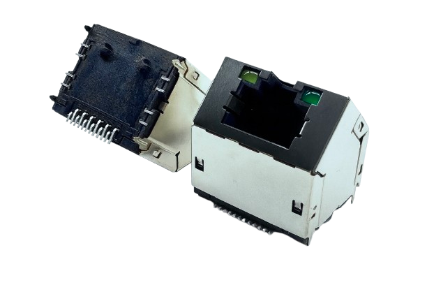
An RJ45 Connector with integrated magnetics saves board space and reduces component count. A version without magnetics requires separate magnetics on the board but allows you to adjust the filtering and layout.
When preparing the parts list for an Ethernet port, the same question often arises: should you choose an RJ45 Connector with integrated magnetics or a version without magnetics and place the transformers on the board yourself? What does the wrong choice cost? Integrated versions save board space and reduce component count but the housing limits the size of the magnetics. Separate magnetics offer more flexibility but leave component selection and layout to you! This article compares the two approaches in terms of board space, EMC, rework and design flexibility so you can assess them against your own requirements.
What Do Magnetics Do in an RJ45 Connector?
Ethernet port magnetics comprise transformers and common mode chokes located between the PHY (physical layer chip) and the network cable. The transformers provide galvanic isolation between the cable and the system. A 1:1 turns ratio is common but the actual ratio must meet the PHY specifications. The common mode chokes attenuate common mode noise in both directions.
Under IEEE 802.3, 10/100/1000BASE-T ports must pass an isolation withstand test, such as 1,500 V AC at 50 or 60 Hz for one minute. The standard also permits an alternative test at 2,250 V DC for one minute. The standard does not explicitly require magnetics but transformers are the most common approach because they meet the isolation requirement at low cost. Magnetics perform four functions:
- Electrical isolation: within their rated isolation capability, they interrupt the direct conductive path between the network cable and the system.
- Signal balance and common mode rejection: they help maintain signal balance within each twisted pair and attenuate common mode noise from the surroundings and the board.
- Impedance matching: they help match the impedance of the PHY output to that of the network cable.
- EMC improvement: 10/100/1000BASE-T commonly uses unshielded twisted pair cable. Common mode noise that is not filtered out can radiate from the cable.
Structural Differences Between RJ45 Jacks with and Without Integrated Magnetics
An RJ45 jack with integrated magnetics contains the magnetics inside its housing. An RJ45 Jack Without Magnetics contains only the jack itself, so the magnetics must be soldered separately onto the PCB. The table below compares the two approaches.
| Comparison | RJ45 jack with integrated magnetics | RJ45 Jack Without Magnetics with separate magnetics |
|---|---|---|
| Magnetics location | Inside the jack housing, forming a single component | Separate components on the PCB between the PHY and jack |
| Component count and assembly | Fewer components and lower assembly costs | More components and assembly steps |
| Board footprint | Smaller footprint, suitable for compact devices | The jack and magnetics occupy separate areas, requiring more space |
| Common mode filtering and crosstalk | Cores are usually smaller and closer together, potentially increasing crosstalk and losses and limiting common mode filtering | Models with larger cores and lower internal coupling can be selected for greater flexibility in common mode filtering |
| EMC shielding | The metal housing encloses the entire module and can shield cable-side signals from internal system noise | Traces between the magnetics and jack are on the PCB, so layout must keep them away from noise sources |
| Rework after production testing | Faults in the magnetics or jack are harder to rework and often require replacement of the entire unit | Only the faulty component needs replacement |
| Design flexibility | Limited to the finished product’s fixed magnetic parameters | Transformer and filter component combinations can be selected independently |
Different magnetics may look almost identical in a schematic yet have very different electrical and EMC performance. Construction quality affects coupling between signal paths on either side of the transformers and common mode chokes. The EMC performance of an integrated version also depends on the product in which it is used and may be better or worse than that of separate magnetics.
Four Factors That Determine Whether to Choose Integrated Magnetics
Evaluate four factors when deciding whether to use integrated magnetics: board space and component count, EMC and crosstalk margins, production rework and flexibility in adjusting magnetic parameters.
- Board space and component count: choose integrated magnetics when space is limited and you want fewer components and assembly steps. Where the contact count is constrained and the PHY connection requirements permit it, consider an integrated module with each PHY-side centre tap individually decoupled through a capacitor before connecting to a single ground contact.
- EMC and crosstalk margins: separate magnetics provide more flexibility in adjusting common mode filtering. Models with lower internal coupling can improve filtering but traces between the magnetics and jack must stay away from board noise sources. The metal housing of an integrated version can shield internal system noise, while smaller and more closely spaced cores may increase crosstalk and losses. The overall result depends on the actual model and application.
- Production rework: if parts may need replacing after production testing, choose a jack without magnetics and separate magnetics so that only the faulty component needs replacement. An integrated version often requires replacement of the entire unit, increasing rework costs.
- Flexibility in adjusting magnetic parameters: choose a jack without magnetics if no integrated version meets the PHY’s magnetic requirements or if the filtering configuration may need changing later. Transformers and common mode chokes can then be selected separately. An integrated version has fixed magnetic parameters when it leaves the factory.
If these factors conflict, such as limited board space combined with tight EMC margins, use EMC test results from the actual system board. Do not decide solely from the datasheet schematic.
Specifications and Layout Checks for Both Approaches
After choosing an RJ45 Connector with either integrated or separate magnetics, check the datasheets and board layout item by item.
When Choosing Integrated Magnetics: Check the Datasheet
The magnetic parameters of an RJ45 jack with integrated magnetics are fixed at the factory. Compare the PHY datasheet’s magnetic requirements with the jack datasheet, checking return loss, turns ratio tolerance, isolation withstand voltage and whether PoE support is specified. Models with the same schematic can perform differently. Before mass production, verification through actual system testing is more reliable than relying only on datasheet values.
When Choosing a Jack Without Magnetics: What Must Be Added to the Board?
- Transformers and common mode chokes: select them according to the PHY datasheet and solder them between the PHY and jack.
- Centre taps: connect the PHY-side centre taps according to the PHY datasheet. Many voltage mode PHYs require each centre tap to connect to ground through its own capacitor; multiple centre taps should not be tied together without approval. Many current mode PHYs require the centre taps to connect to a specified supply voltage. Do not determine the connections from the drive mode alone.
- Bob Smith termination: a common mode termination resistor network connected to the cable-side centre taps reduces common mode currents between pairs. A high voltage capacitor is also connected between the resistors’ common point and chassis ground to filter residual noise that passes through the transformers.
- MDI routing: keep traces between the magnetics and jack away from board noise sources. Otherwise, board noise can couple into signals that have already been filtered and cause EMC problems.
Frequently Asked Questions
Q: Can an RJ45 Connector without integrated magnetics connect directly to a network?
A: Usually not. An RJ45 Connector without magnetics contains no transformers, so the usual approach is to add separate magnetics between the PHY and jack. Magnetics provide isolation and common mode rejection. Although the standard does not explicitly require them, they are the most common way to achieve the 1,500 V AC isolation withstand requirement. Some enclosed backplane or short distance interconnect designs use capacitive coupling instead. However, capacitor voltage ratings alone do not establish that a port complies with Ethernet requirements. Isolation and signal performance must be verified for each design using the PHY manufacturer’s guidance. The AC and DC withstand tests mentioned above are alternatives; passing both is not required.
Q: How should magnetics be selected for an RJ45 Connector that supports PoE?
A: For an RJ45 Connector that supports PoE, select magnetics whose datasheet explicitly specifies PoE support. Under PoE, the MDI pairs used to carry power have a common mode DC voltage. The Bob Smith termination resistors must be isolated from this DC supply potential using DC blocking capacitors. This applies to both integrated and separate magnetics. First confirm PoE support in the datasheet.
Q: How do you choose between 8-core and 12-core magnetics for an RJ45 Connector?
A: In four-pair Gigabit Ethernet magnetic modules, an 8-core design typically has one transformer and one common mode choke per pair. A 12-core design adds an autotransformer to each pair, giving three cores per pair. An 8-core design is usually less expensive but may require more careful layout and EMC tuning. A 12-core design can help in some systems with higher noise levels. Both must be selected according to PHY compatibility, PoE support and system-level EMC requirements. Core count alone is not sufficient.
Q: Is it better to place the common mode choke on the PHY side or cable side?
A: Follow the datasheet and reference design for the selected PHY. Application guides for some Gigabit Ethernet PHYs recommend placing the common mode choke on the cable side of the transformer in new 8-core designs because testing showed less PMA compliance waveform template margin with a PHY-side choke. This is not a universal rule for all PHYs. Existing designs that have passed the applicable system tests may continue using their current configuration.
Choosing an RJ45 Connector with or Without Integrated Magnetics: Start with Board Space and EMC Margins
When choosing an RJ45 Connector with or without integrated magnetics, first assess board space and component count, then EMC margins, rework requirements and flexibility in adjusting magnetic parameters. Choose integrated magnetics when space is limited and fewer components are desired. Choose a jack without magnetics and separate magnetics when you need more flexibility in common mode filtering and the ability to replace individual components.
Once you have determined the board dimensions, port count and speeds, and whether PoE is required, contact Walta Electronic. If standard models do not meet your specifications and you need a Custom Connector Manufacturer, Walta Electronic provides complete OEM/ODM support from product design, tooling development, prototyping and testing through to mass production. Call or email with your requirements to confirm suitable models and the feasibility of customisation.
Walta Electronic
Tel: 886-2-2657-7778
Email: inquiry@walta.com.tw
Address: 3F-2, No. 15, Lane 360, Section 1, Neihu Road, Neihu District, Taipei City, Taiwan