
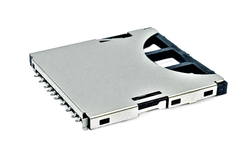
SIM card connectors and MicroSD card connectors are PCB interface components with different roles. Selection should be based on three factors: signal specifications, available layout space and insertion and removal frequency.
When a product specification lists both a SIM card connector and a MicroSD card connector, how do you decide which one to keep on the PCB? Both look like low-profile card sockets, so is it enough to simply choose one that fits?
From a PCB design perspective, these two components address entirely different needs: one provides cellular network connectivity, while the other expands storage capacity. Choosing the wrong mechanism can lead to costly rework if an eject hole is found to be misaligned with the enclosure opening after mass production begins. The signal interfaces, mechanical space requirements and design considerations for insertion and removal frequency are all different. These are the three factors engineers need to verify during connector selection, rather than starting with the appearance of the card slot.
What Is the Difference Between SIM Card Connectors and MicroSD Card Connectors? Start with Their Basic Roles
A SIM card connector is a PCB interface component that holds a cellular SIM card and allows the communication module to connect to a mobile network. A MicroSD card connector holds a MicroSD memory card to expand the device’s storage capacity. The two connectors serve entirely different signal paths in the circuit design.
SIM card connectors are commonly used in IoT communication modules, vehicle communication devices and asset trackers that need cellular network connectivity. MicroSD card connectors are commonly found in dash cameras, industrial cameras and data acquisition devices that require local storage or data backup.
This also explains why consumer smartphone guides often discuss the two together. A phone’s dual-card tray can accommodate both a SIM card and a memory card, but PCB designers still need to address the separate signal pin assignments, card ejection mechanisms and contact service life. Sharing a tray does not resolve all of these requirements.
| Comparison | SIM Card Connector | MicroSD Card Connector |
|---|---|---|
| Primary function | Connects a cellular SIM card so the communication module can access a mobile network | Connects a MicroSD memory card to expand device storage |
| Common mechanisms | Push-pull ejection; enclosed insertion (non-eject) | Push-push ejection; hinged |
| Design for insertion and removal frequency | Industrial grade: typically 5,000 cycles or more; consumer grade: approximately 1,500–3,000 cycles | Typically 5,000–10,000 cycles |
| Typical applications | IoT communication modules, vehicle communication devices and asset trackers | Dash cameras, industrial cameras and data acquisition devices |
Factor 1: Differences in Signal and Interface Specifications
Differences in signal and interface specifications are the first factor to check when selecting a connector. A SIM card connector connects to the communication module’s UICC interface and carries signals used by cellular communication protocols. A MicroSD card connector connects to an SD/SPI interface and uses protocols for accessing data on a storage device. Their pin assignments and electrical characteristics are not interchangeable, so they should not be treated as the same type of component simply because both are low-profile card sockets.
If the application requires greater capacity or faster transfer speeds, an SD card connector can also be considered. However, its mechanical dimensions are larger than those of a MicroSD card connector, so products with limited PCB space generally favor the MicroSD format. SIM cards also come in different sizes, including standard SIM, Micro SIM and Nano SIM. Before selecting a SIM card connector, confirm which card size and pin assignments the communication module supports. This helps avoid choosing a socket that fits the card mechanically but has signal pin assignments that do not match the module specification.
Factor 2: Mechanical Space and PCB Layout
Mechanical space and PCB layout are the most common sources of difficulty during prototyping. SIM card connectors commonly use two mechanisms: push-pull ejection and enclosed insertion (non-eject). The former requires an eject hole in the enclosure and clearance for the ejection mechanism to operate. The latter does not require an eject hole but the card must be installed during assembly. MicroSD card connectors commonly use push-push ejection or hinged mechanisms. A hinged design adds a sealing interface for dust and water protection, but requires more vertical space than an ejecting design.
If the same PCB also needs a USB Type-C connector or other I/O interfaces, plan the combined connector footprints and height allowances in advance. This helps prevent interference between the ejection mechanisms of the SIM and memory card sockets. Also check that the enclosure openings align with the actual connector positions on the PCB, as this is a common source of alignment errors during prototyping before mass production.
Factor 3: Usage Frequency and Contact Service Life / Supply Chain Costs
Usage frequency and contact service life are the factors most easily overlooked. SIM cards are generally replaced infrequently during a device’s lifetime, particularly in IoT or vehicle communication modules where they may remain installed for extended periods. A very high mating-cycle rating is therefore not essential, but long-term contact stability is required. MicroSD cards are often used for data backup or retrieving recorded data, so users may regularly replace them to read the contents. This results in a significantly higher insertion and removal frequency and calls for a more durable connector mechanism.
Typical industry specifications list industrial-grade SIM card connectors with mating-cycle ratings of 5,000 cycles or more, while consumer-grade versions commonly range from 1,500 to 3,000 cycles. MicroSD card connectors typically range from 5,000 to 10,000 cycles. The assessment generally considers whether contact resistance exceeds approximately 50 milliohms (mΩ) as the number of insertion and removal cycles increases. Gold-plated contacts with a nickel underlayer generally offer better mating durability and oxidation resistance than tin or silver plating, especially in MicroSD applications involving frequent insertion and removal. From a supply chain perspective, if a SIM card connector or MicroSD card connector requires a customized pin count or mechanical dimensions, tooling and engineering sample lead times should be included in the product development schedule early. This helps avoid delays to mass production caused by late specification approval.
Frequently Asked Questions
Q: Can a MicroSD card connector be used as a direct replacement for a SIM card connector?
A: A SIM card connector cannot directly replace a MicroSD card connector. Their pin assignments, signal protocols and ejection mechanisms are entirely different. If a product requires both network connectivity and storage expansion, the PCB must provide the corresponding routing and space for each.
Q: How does a Nano SIM card connector differ from a standard SIM card connector?
A: The main differences are card size and PCB footprint. Nano SIM is the smallest format currently available, allowing a smaller connector body that suits portable or wearable devices with limited space. Standard SIM cards are larger and offer comparatively consistent mechanical robustness and insertion and removal feel. They remain common in some industrial equipment.
Q: Is a push-push or hinged MicroSD card connector the better choice?
A: There is no single best mechanism for every MicroSD card connector application. The choice depends on the device’s dust and water protection requirements and insertion and removal frequency. A push-push mechanism is intuitive to operate and has a lower profile, making it suitable for frequent card changes in applications where the enclosure does not require additional protection. A hinged mechanism adds a sealing interface at the lid, making it more suitable for industrial cameras and outdoor devices that require a dust and water protection rating. However, it is slightly taller than a push-push mechanism, and the PCB layout must allow clearance for the lid to open.
Q: How is a connector’s mating-cycle rating defined?
A: The mating-cycle rating uses a contact resistance threshold to determine the end of service life. A common industry practice is to continue insertion and removal testing until contact resistance exceeds approximately 50 milliohms (mΩ), at which point the connector is considered to have reached the end of its service life. Gold-plated contacts with a nickel underlayer generally provide better oxidation and wear resistance than tin or silver plating, resulting in a longer mating-cycle life. This is one reason industrial-grade connectors often use gold-plated contacts.
Q: What routing considerations apply when SIM card connectors and MicroSD card connectors are placed on the same PCB?
A: The two interfaces should be routed separately when SIM card connectors and MicroSD card connectors share a PCB. Their signal characteristics differ: SIM cards carry the communication module’s control signals, while MicroSD cards carry data transfer signals. If trace lengths, grounding and shielding are not planned separately, noise can occur during high-speed data access. During layout, verify that the two interfaces have independent signal paths and ground return paths.
Choosing a SIM Card Connector Starts with the Product’s Signal Requirements and Usage Scenario
Choosing SIM card connectors and MicroSD card connectors ultimately comes down to three factors: signal and interface specifications, mechanical space and PCB layout, and usage frequency and contact service life. First determine whether the product needs cellular connectivity, whether the enclosure has room for an eject hole and whether users will frequently change the card. These answers will guide the selection, rather than simply copying a smartphone specification.
As a connector manufacturer in Taiwan, Walta Electronics has long been involved in the design and manufacture of memory card sockets, including SIM card connectors and MicroSD card connectors. As a custom connector manufacturer, we can adapt designs to suit the product’s pin configuration, mechanism type and available PCB space. If you have questions about signal specifications or mechanism selection, share your preliminary circuit layout and enclosure opening requirements with our engineering team for custom design recommendations and engineering sample evaluation.
Walta Electronic Co., Ltd.
Tel: +886-2-2657-7778
Email: inquiry@walta.com.tw
Address: 3F.-2, No. 15, Ln. 360, Sec. 1, Neihu Rd., Neihu Dist., Taipei City 114, Taiwan